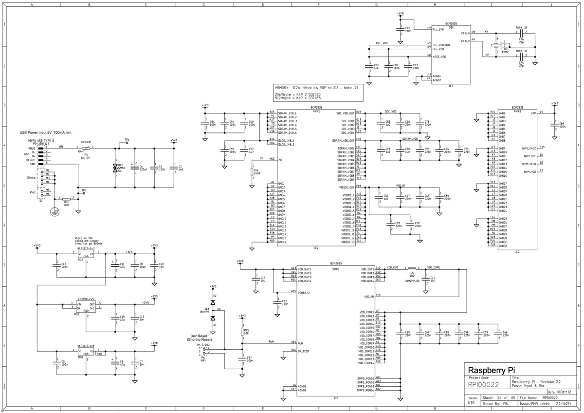
Raspberry Pi Pcb Schematic
Turns out the pi camera does not have publicly available schematic or pcb designs. 23 rows for raspberry pi 3 model b+, the pcb technology has been changed to provide better heat.

Raspberry Pi project ideas let Raspberry Pi make phone
The raspberry pi 4 model b is the latest board launched by the raspberry pi foundation in june 2019.

Raspberry pi pcb schematic. That is the core system design, next up is the schematic layout and then pcb layout. Raspberry pi hat modules are a great open standard for adding functionality to a pi that either needs additional hardware, or a better way to connect with the rest of the world. I hope you will understand on looking at this why the.
Note the physical pin numbering is shown in figure 4, for the pin allocation see figure 2 or the full raspberry pi pico schematics in appendix b. You cannot buy the broadcom chip (s) the pi is based on, unless you want to buy a few million of them. As promised, here are the gerbers (a visualisation of the printed circuit board or pcb) for the finalised version of the raspberry pi.
A few rp2040 gpio pins are used for internal board functions, these are: Rather than be an affordable desktop placement like the traditional raspberry pi, the cm4 is intended for industrial applications where the module is embedded into a custom pcb and enclosure. The newest model, the raspberry pi zero, sold out almost immediately, and provides the computing power of a full raspberry pi (including a 40% higher cpu clock speed at 1ghz) in a.
Gpio29 ip used in adc mode (adc3) to measure vsys/3 gpio25 op connected to user led Attach cd1_scl (j6 pin 39) to gpio1 (j5 pin 3). If you want to use the lite version in your project you'll have to make a few changes to the design, and that includes adding a micro sd card.
Raspberry pi power on led status ok led. Attach cam1_io0 (j6 pin 43) to gpio3 (j5 pin 7). A strong cooling arrangement like the one present in a commodore 64 permits the broadcom bcm2711c0 processor of raspberry pi 400 to be timed at speeds of 1.8 ghz thereby enhancing its efficiency.
Here is the schematic for my rpi pico debugger shoe. So you assume with all the openness of the raspberry pi foundation that there most popular peripherals would be open hardware, but you would be wrong. Raspberry pi pico pinout 7.
Attach cd1_sda (j6 pin 37) to gpio0 (j5 pin 1). To get started with the raspberry pi compute module you are going to need the following parts: I get several messages every day asking what it can possibly be that we are still working on:
Attach cam1_io1 (j6 pin 41) to gpio2 (j5 pin 5). Own pcb design based on raspberry pi 4 schematic. The console pc highlights 4 gb of lpddr4 ram.
Raspberry pi pico rev3 board. This processor uses 20% less power and offers 90% greater performance than the previous model. You can find a pdf version of it here.
Raspberry pi or rpi zero 2w is the second generation zero board released by the rpi foundation. A few notes about the schematic: I used a usb micro b connector so that it matches the pico.
It is anything but a custom raspberry circuit board from the current raspberry pi 4 pcb, explicitly renovated with a console connected. Smps to generate the 3.3v for the rp2040 and its gpio. Reversed schematic and pcb of raspberry pi camera v2.1.
On 17 april 2017 at 22:57, clay mcclure ***@***.***> wrote: Wed jul 01, 2020 12:08 pm. Since 2013 the raspberry pi foundation has been continuing to develop their products with cadence tools, specifically using the orcad and allegro schematic pcb design suites.
The project is here to fix that. Now that there are raspberry pi boards in the wild, we thought it would be a good time to share our schematics with the world.
Raspberry Pi Project Ideas How I Built Call Mom Button
Making a Simple Soundboard with Raspberry Pi Make


Adafruit Learning System
> circuits > raspberry pi l33515 Next.gr
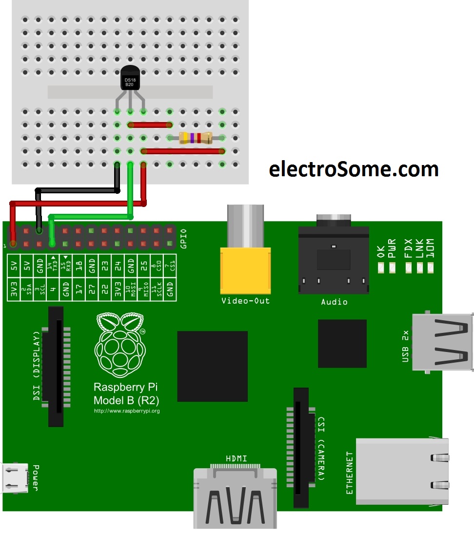
Interfacing DS18B20 Temperature sensor with Raspberry Pi
Raspberry Pi 5 Circuit Diagram Raspberry Paul

Raspberry Pi • View topic Colourcoded PCB photos

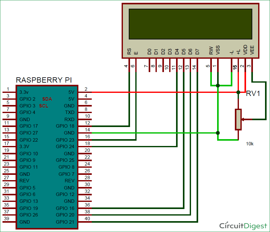
webcontrollednoticeboardusingraspberrypicircuit

Adafruit Learning System
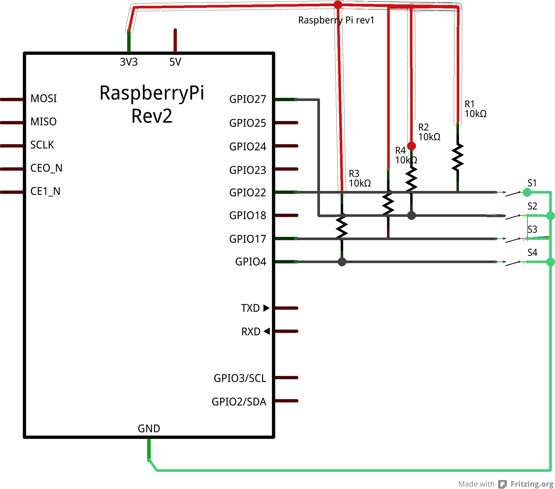
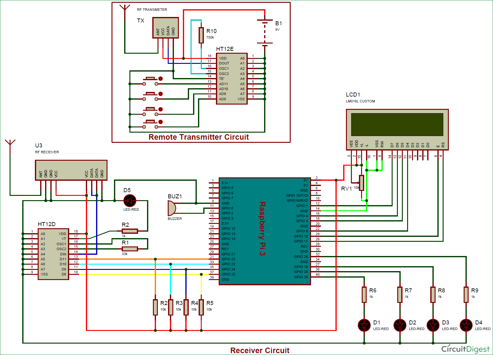
RF Remote Controlled LEDs Using Raspberry Pi

Circuit Diagram Mini Mac Pi Adafruit Learning System

Raspberry Pi 3 Pcb Layout PCB Designs

Raspberry Pi Pico One Tiny Fast Microcontroller ProtoPIC

Circuit of HBridge Motor Driver in Raspberry Pi using
Pin on Raspberry Pi Projects
Schematic help Unknown capacitors for Raspberry Pi

Schematic representation of the circuit. The Raspberry Pi

Adafruit Learning System
Control Raspberry Pi GPIO with Adafruit IO to trigger an LED
